- Cell Broadcast Service or Public Warning System in 5G - July 10, 2020
- 5G Security (5G AKA Authentication) - January 20, 2020
- 5G Network Identity SUPI/SUCI - May 15, 2019
Network Architecture Diagram

Functional Split of NW entities
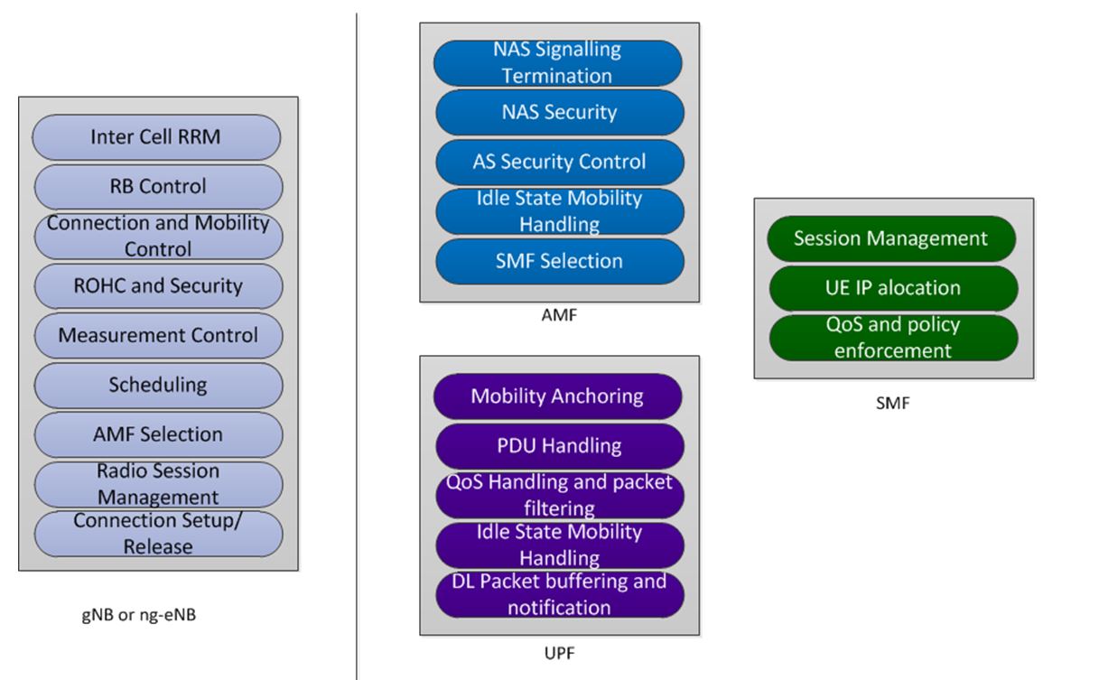
Above Network functions performed by different 5G Access Network entities
Protocol Stack on different interfaces

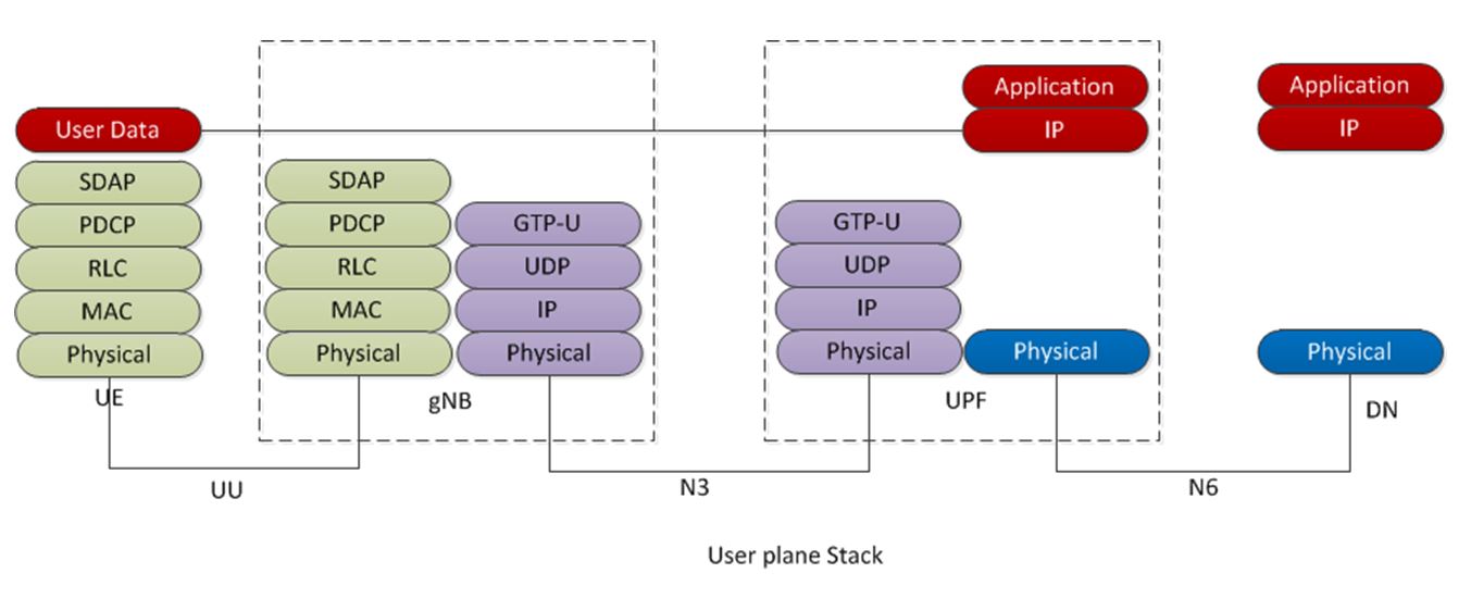
UU User-plane : Radio interface user-plane carries, user Application traffic, which follows UU-U (Above)protocol stack. User-data is transparent to access nodes like gNB.
UU Control-plane : in control plane RRC, PDCP, RLC, MAC, PHY get terminated at gNB, but NAS termination point is AMF, so gNB transparently passes the NAS messages to AMF.
NG Control-plane(N2): this protocol stack is between gNB and AMF. This stack helps providing access to UE to core network and transports NAS messages. Also helps establishment of user-plane tunnels for UE.
NG User-plane(N3) : This is the protocol stack between gNB and UPF. This stack carries user data over GTP-U tunnel established during session establishment over N2.
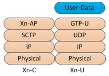
Xn user and control plane : Xn interface is between 2 gNBs or gNB-Ng-eNB. This does necessary signalling and data during mobility.
N4 Interface: This interface is between SMF and UPF, Used for UPF selection and setup of U-plane tunnels and enables PFDs on user plane entities.
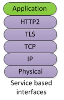
Service based interfaces: Most of the core Network entities with Service based end points and they host services performed by them and exposed these services by REST APIs. Details are in below diagram.
Service Based Architecture
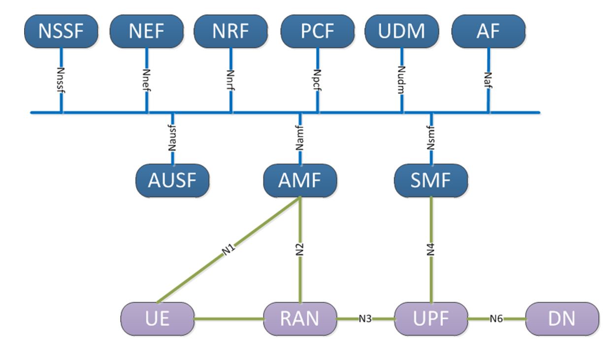
In Service based Architecture, Network functions(Ex AMF) opens up services using service based access point(Namf) and other authorized network functions(Service Consumers) access this service through service these service access points. These interfaces are driven by REST APIs(HTTP)
6 Comments